Sunday, September 25, 2016

You're Fired!

I decided to pulled the spark plugs to make it easier to rotate the crankshaft while I was replacing the push rod guide plates. It's a good thing I did, mainly because one of them was loose.


Cylinder number 4 couldn't have been firing too well with some of the exhaust gases blowing out around the plug. The entire plug is covered with soot except the part covered by the boot. The rest of the plugs look pretty good with a nice healthy tan color, although 1 and 3 are kinda light. A few of them have fresh oil around the base and threads which means the valve cover gaskets are leaking a little so I ordered new gaskets along with new plugs.

My new push rod guide plates arrived; they're the correct 5/16" instead of the the 3/8" somebody else installed. You can read my previous post concerning the push rod guides here. I set one on top of an existing one to check the fit (yes it's upside down).


Looks much better. If I centered one rocker over the valve stem the other rocker aligned almost perfectly, something that couldn't happen with the bigger guides. Here's what the oversized guides look like:


It's a bit of work to replace the 8 guide plates, mainly because you have to adjust the rocker arms, which in turn requires you to rotate the crankshaft until each cylinder is at top-dead-center. The harmonic balancer has a marking for TDC but that only works for cylinder #1 (and also #6). I needed markings for the other six cylinders.

The firing order for the Ford 289 Windsor is 1-5-4-2-6-3-7-8. Being a four-stroke engine each cylinder fires once for every two revolutions of the crankshaft. With all eight cylinders firing once every 720 degrees of revolution you get a single cylinder firing every 90 degrees. So I needed markings on the balancer for 90, 180, and 270, measured from TDC. The balancer has a diameter of 6.375" (ok, I looked it up) giving a circumference of almost exactly 20". Wow, that makes things easy. All I needed were marks every 5" around the balancer. I even labeled them so I could be certain I had the right cylinder.

Just turning the crankshaft to TDC for cylinder #1 doesn't mean it's in the correct position to adjust the rocker arms. It could be 360 degrees off. To ensure both the intake and exhaust valves are closed the distributor rotor needs to be pointing at the #1 spark plug wire.

Since replacing the guide plates was going to be tedious I set up a little routine so I wouldn't overlook anything.
1. Start at TDC for cylinder #1.
2. Remove the rocker arm retaining nuts and then lift off the rocker arm for the two valves. I set the left rocker arm on the left side of my parts tray and the right one on the right side so they would go back on the original side.
3. Use a breaker bar to remove the rocker arm studs. They must have been installed with thread locker instead of thread sealant. I kept the left stud on the left...
4. Clean the threads on the studs where they go into the head.
5. Remove the old guide plate.
6. Clean the threads in the head (as best as I could).
7. Place the new guide plate in position.


8. Coat the stud threads with Teflon (PTFE) paste thread sealant before hand tightening each stud. When I removed the studs most of them came out with dry threads but a few were wet. You can see in the picture that these studs do indeed screw into a water jacket so thread sealant, not thread locker, is required.
9. Torque the studs to 60-70 ft.lbs. Before tightening I pulled down on the guide so it wouldn't be cocked to one side since there is some play.
10. Oil the push rod end, stud threads, and valve stems in case you wiped them clean.
11. Install the respective rocker arms and retaining nuts.
12. Adjust each rocker arm. Tighten the retaining nut until the rocker arm becomes snug on the push rod. Then add 1/2 to 3/4 of a turn more to set the pre-load on the lifter.
13. Squirt some oil on both ends of both rocker arms as down around the pivot areas.
14. Rotate the crankshaft clockwise 90 degrees and repeat the steps for the next cylinder in the firing order.


The rocker arms on the right have the new plate installed and align with the valves nicely. The two on the left still have the wrong guides. Yikes.

While I was doing all this work I also wanted to check the rocker arm geometry to make sure the push rods were the correct length. This is easily done by coloring the top of a valve stem with a marker, assembling the rocker arm, and cranking the engine a few turns to check were the rocker touches the valve stem.


Above is a closeup off the #1 exhaust valve stem. After I adjusted all of the rocker arms I turned the crankshaft another 90 degrees to put the #1 cylinder back at TDC. When I had first adjusted #1 I had colored the valve stem tip with a marker before assembly. You can just barely see the horizontal line where the rocker arm contacted the valve stem while I was hand-cranking the engine through 2 revolutions. It's not super important that the wear pattern is centered on the valve stem as long as it's close. What is important is that the thickness of the line is as small as possible, meaning the minimum amount of friction. If the push rods weren't the correct length the wear pattern would have been wider.

Thursday, September 22, 2016

Holy Cowl!

Early Mustangs are notorious for having rust in the cowl area, usually so bad that rain water drips inside the car and rusts out the floor pans. I can't see any evidence of a leak but then again this car probably hasn't seen any rain in many years. It did drizzle a little on my lone trip but not enough to make me roll up the windows. From the outside the center cowl area looks clean with a texture on the bottom which is probably some kind of sealer, but it's impossible to see the sides where the fresh air "hats" are located and where rust usually occurs.

The driver side vent was working very stiffly and looking up under the dash I could see it had some surface rust. I decided to remove the vent and spiff it up while at the same time get access to the bottom of the cowl.


Here's the nasty looking vent. The rust is mainly at the top were it bolts to the cowl, but at least the rubber seal is still pretty pliable.


This is the bottom of the cowl looking up through the hat. Water is supposed to run around the hat and drain down the side of the car behind the fender, while fresh air blows through the hat down into the vent assembly. At first it didn't look too bad for being 50 years old but when I scraped off the flakey rust it got worse.


Using a small mirror I was able to look on the other side of the hat at the horizontal surface of the cowl. It looks like the the rust is limited to the hat as the flat parts look really good. Fortunately this is a common problem and there is a repair kit available.


These replacement hats fit inside the originals and will never leak if sealed correctly. I will NOT be using the silicone sealer that comes with the kit as it contains an acid to help it cure but can be corrosive to steel. I ordered some body sealer to use instead. I debated whether to cut out the old corroded hat or leave it like the kit instructions say. I think I'll cut it out since it's not going to be a benefit to the repair, and more importantly, I'll be able to seal the rest of the cowl area with it out of the way.


Before I started I coated everything with Corroseal Rust Converter just because it's fun watching rust turn black. Then I used a 3" cutoff wheel in my pneumatic die grinder to cut the hat off. I tried to cut as flush as possible without damaging the horizontal flange so as to minimize any lip that could trap water.

Btw, in order to work on this area, I have to lay on my back with my head and right arm under the dash, my feet in the back seat (I had already removed the driver's seat, steering wheel, and pedals). It's extremely awkward just taking these photos let alone actually working on anything.

Three songs later (about 10 minutes) and it was over.


You can see the rot was much worse on the side I couldn't see (it's upside down). I used a mirror to assess any remaining damage.


This is the horizontal surface on one side where water sits and rust-through would have been a serious problem. Not too bad.


Here's a view looking towards the outside opening of the cowl. As you can see there is very little rust. The next step was to clean and prep everything I could reach before treating it with the rust converter. I took my time here as I wanted to get rid of as much rust as possible before coating the surfaces with body sealer. Then I can seal in the new hats.


I dry fit the new hat before sealing it in place. For some reason that one stud was bent so I had to straighten it out.


Here's the fresh air vent after I spruced it up.


And here's the results of all my labor. I know it's not much to look at, but you can see the vent in place. I'll eventually get around to doing the passenger side cowl, but since it requires removal of the heater assembly I'll wait until I install the A/C.

Wednesday, September 21, 2016

Rust Never Sleeps, or does it?


When I treated my brake and clutch pedals I followed the directions closely. First, I brushed off all of the loose rust with a wire wheel in my drill, then the wiped them down with some diluted Simple Green.

Here are close ups of the two pedals before applying Corroseal.


And here they are after one coat of Corroseal before I painted them.


With the pedals fitted in the new support bracket I noticed the brake pedal stop (the part with the rectangular hole) was hitting the bolt for the clutch pedal stop. Somebody had bent it over so it wouldn't rub on the side of the old bracket, which it was sure to do with the crooked shaft.

I was curious about how the rust conversion would work with little to no surface prep and I had the perfect test piece, my old pedal support.


On the clutch side, with the elongated hole, I spent a couple of minutes with a wire brush and then wiped off the "rust dust."


On the the brake side I left all 50 years of patina in place.


The application of the rust converter was a little more difficult since the surface wasn't nearly as smooth as it could have been had I used the wire wheel. I also noted that the cup I was using to dip my brush was becoming contaminated much more quickly. After one coat here are the results.


Not bad for maybe 10 minutes of effort, but still not acceptable. Some of the rusty areas were fully neutralized but a lot of rust still showed. So I applied a second coat which went on very easy and only took a few minutes.


Now we're talking! To really put this rust converter to the test, I'll top coat half of it with spray paint and then leave it outside for a while and see what happens. Stay tuned...

Clutch Support


Déjà vu. This is the clutch pedal shaft where it go through the support bracket. My previous Mustang back in 1980 suffered from the same problem as Ford used an inexpensive pot-metal bushing with a plastic liner that just wasn't up to the task. Once the bushing fails the shaft starts grinding away as the bracket, even cutting a groove in the shaft.


With the shaft being so crooked, the pedal is also crooked making the linkage bind. Since the brake pedal shares the same shaft it has the same problems.


Here are the clutch and brake pedals after I did a quick brushing with the wire wheel to remove any loose rust, then wiped them down. I then applied Corroseal Rust Converting Primer.


It's water based and goes on with a brush. It kind of looks like watered down Elmer's Glue. In just a few minutes the magic starts to happen.


Any surface rust gets converted to magnetite which protects the metal and keeps it from rusting any further. After they dried I sprayed the two pedals with black trim paint.


Here's a closeup of the new pedal support showing the problematic bushing. I'm not trusting this one bit so I picked up an improved bushing set that uses actual needle bearings.


I first had to remove the stock bushing using my Dremel to grind off the 10 little tabs.


A few good whacks with my hammer and the bushing fell right out. Here's the new bearing next to the old bushing.


And finally, two shots of the finished pedal assembly.


Custom Sequential Tail Lights

Here's a pic of my tail lights with the brakes applied. As you can see they're not very bright. They do sequence nicely, in three segments.


They appear to be totally custom since they're sealed to the body with silicone. The housing inside the trunk doesn't have any light bulb sockets; the wires go straight through the housing. Hopefully they're LED so I don't have to worry about changing bulbs. If I can't find a way to add more LEDs to make them brighter I'll have to swap them out for safety reasons. Unfortunately, the rear panel was hacked up to make room for the lights so I may not find a bolt-on replacement. 

Maybe something like this:


Whoops, wrong pic. More like this:


These are '65 Thunderbird lenses which were also reused later on the '68 Shelby and California Special Mustangs. My lenses look to be way bigger than the cutout so these may work. Future project...

UPDATE:

I just found the lenses on the National Parts Depot website.


Apparently they replace the stock lens without any modification. I guess only the outer third would light up.

I also found a part number on the housings, SF-3670442 & SF-3670443. Apparently these are for a 1974 AMC Matador; the internal electronics and LEDs are obviously not.

UPDATE 2:

I finally took the plunge and decided to tackle removing the tail light housings inside the trunk. They were attached to the body with what looked like hot glue and silicone but could have been an epoxy. I used a utility blade to slice between the housing and the body until I could gently pry it off.


Here's a shot of the LED panel attached to the inside of the housing.


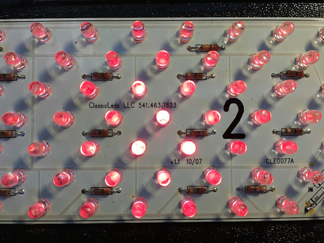
If you look close you can see the panel is made by ClassicLEDs LLC. Unfortunately, it doesn't look like I can modify this to make it brighter.


Here's a picture with just the parking lights on. I couldn't take a picture of the brake lights since I'm not quick enough but they are much brighter. Since this panel is not a one of a kind and I haven't found any other complaints about them being too dim I've decided to go ahead and keep them and just replace the tail light lenses. There are several vendors selling a kit to fit the '68 Shelby lights to a '65 or '66. All of these kits appear to use this same LED panel, although mine is only version 1.1 lol.


Here's a shot from the inside of the trunk looking through the lenses that are siliconed to the body. You can see how the chrome strips on the outside block around 33% of the light passing through. Plus the chrome strips can cause a glare which makes the LEDs seem that much dimmer. So hopefully swapping these lenses for the Shelby tail lights will help the LEDs put out more light. I'm pretty sure I'll end up with some screw holes in the back panel that won't be covered by the new tail lights. We'll see how it goes.

UPDATE 3:

After much debate I finally ordered new tail lights from Mustang Depot. The kit came with lenses, chrome trim, tail lamp housings, gaskets, and hardware.


I don't actually need the housings that mount in the trunk, but my AMC housings look out of place. Once the parts arrived I worked on removing the old tail lights.


Removing the old lenses wasn't as hard as I thought it would be. They were mounted to the rear panel with 4 screws, some double-sided tape, and what appeared to be urethane caulk. I just took my time slicing around the edge with a utility blade and then slowly pried the lens away.


On the back of the old lens you can see some rust on the metal tabs that hold the trim strips on. The strips appear to be stainless steel but the manufacturer skimped out on the mounting tabs. With the way the lens was sealed to the body, there wasn't any way for moisture to get behind the panel except through the holes for the trim, and through the mounting screw hole in the upper left. I'm actually surprised to find any rust here, but just a simple car wash would allow moisture to get trapped behind the lens. Whoever installed these lights also mounted a piece of clear plexiglass on the inside of the cutout hole that you can see in the next photo. I'm guessing this was to keep water out of the trunk.


Here's what the new tail light trim looks like in place. While it doesn't cover the 2 holes on the left (from the housing mounting screws), what you can't see is the 1/4" gap on the right. The cutout in the body is just slightly bigger than the new lens. This gap is beyond my bondo skills, and replacing the rear panel with new sheet metal is a major job. I thought about covering the entire rear with a 6" with piece of brushed aluminum and cutting new holes, but ultimately decided to go with a fiberglass panel that mimics the panel that Shelby used in 1968.


This new panel will still require lots of prep and paint, but I'll be able to take it somewhere, have it painted professionally, and then mount it myself. It attaches with just a few screws across the top, which will be hidden under the trunk lid, and along the bottom behind the bumper. The lights themselves will also help secure the panel in place.

Besides solving my problem, this panel serves another purpose. The '65 Thunderbird chrome trim piece only covers the rearward facing surface of the lens, which is around 1/2" thick. When mounted on a flat surface, like my Mustang, this portion of the lens between the body and the trim is exposed. On the T-Bird the lens was surrounded by other trim pieces so the edges of the lens couldn't be seen. Shelbys and California Specials utilized this molded panel to make the lens appear recessed while hiding the exposed edges.

While waiting for my tail light panel to arrive I took the time to clean up the rear of the car. When my car was last painted around 10 years ago, they buffed out the paint and left white compound in all kinds of seams and panel edges. After 10 years that compound is rock hard and almost impossible to remove. Almost. I tried water, Simple Green, quick detailer, and cleaner wax, but nothing touched it. Until I tried rubbing alcohol. Simply amazing! The dried up compound wipes right off. So as I was cleaning up around the trunk area I found that the rubbing alcohol removed more than the compound.


There are more than a few spots on my car where the paint looks dirty but won't come clean. I've tried polishing the spots but they wouldn't go away leading me to think it was overspray from the strips. However, the amazing rubbing alcohol even removed the dirty haze.


The black tape is leftover sticky stuff from the old lights, but you can see how the shiny, dirty haze came off around the trunk opening.

The new tail light finally came in and when I held it in place I got an idea of the trimming that would be required.


I used a paper template to transfer markings where I needed to cut the panel, then used a cut-off wheel on my die grinder.


Of course, there was a lot of trimming required. I made sure to remove small bits at a time.


I even had to trim about 3/8" all the way across the top edge in order to make the fiberglass sit flat on the sheet metal.


When I got the panel fitting as well as I could I discovered the trunk lid wouldn't close all the way. As a compromise I had to raise the latch about 1/4".


Here's what it looks like with everything in place but the rear bumper. The trunk isn't latched in this picture so it looks way off.


For now I decided to spray the panel with satin black trim paint. I can always repaint it later.